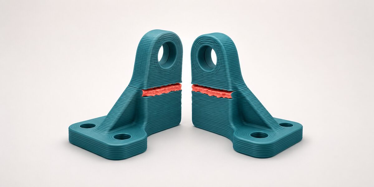
A 3D-printed part can look nearly perfect and still break earlier than expected. The dimensions may be correct, the surface may be clean, and the infill may appear solid. Yet when the part is placed under load, it can separate along a layer boundary.
This is not necessarily a printer malfunction or a bad spool of material. It is often a consequence of how material-extrusion printing builds an object: one deposited line and one layer at a time.
Understanding this directional behavior is essential when printing brackets, fixtures, replacement parts, tools, test specimens, or any other component expected to carry a load.
Why strength changes with direction
During material-extrusion printing, the nozzle deposits a softened thermoplastic line onto material that was placed moments earlier. The new line must contact and bond with the previous one before the interface cools too far.
This interface is commonly called an interlayer weld. It is not an adhesive joint. The bond develops as the deposited materials make contact and polymer molecules move across the interface.
The effectiveness of that process depends on several interacting conditions, including:
- The temperature of the incoming material
- The temperature of the previous layer
- Printing speed and material flow
- Layer height and line width
- Cooling rate and surrounding air movement
- Material formulation and condition
- The time between neighboring deposits
Because each layer contains continuous deposited lines, a part can behave differently depending on the direction of the applied force. Engineers call this behavior anisotropy, meaning the material does not have identical properties in every direction.
For practical purposes, the important lesson is simple: a printed part is not automatically as resistant to being pulled across its layers as it is to being loaded along continuous extruded lines.
Consider orientation before increasing infill
Increasing infill is a common first response when a functional part breaks. It can help in some situations, but it cannot correct every weak load path.
Consider a mounting bracket with a narrow upright section. If the bracket is printed upright, its layers may cross the narrow section horizontally. A bending force could then try to open those interfaces one after another.
Rotating the component may allow longer deposited lines to follow the primary load path. This can make the part less dependent on a small number of interlayer bonds.
Orientation involves tradeoffs. A stronger orientation may require more support material, produce a rougher surface on one side, or change the accuracy of holes and mating features. The best orientation therefore balances:
- Expected loading direction
- Interlayer separation risk
- Support requirements
- Surface-finish requirements
- Dimensional accuracy
- Printing time and material use
The goal is not simply to place the largest surface on the build plate. It is to arrange the layers so that normal use does not unnecessarily pull them apart.
Strength begins with the part geometry
Printer settings cannot rescue a geometry that concentrates too much stress in one small location.
Sharp internal corners, sudden thickness changes, small holes near edges, and thin transitions can all become starting points for cracks. Once a crack reaches a weak layer boundary, it may travel through the part quickly.
Several design changes can produce a more useful improvement than adding material throughout the entire interior:
- Add fillets where walls meet
- Use gradual thickness transitions
- Increase the number or thickness of exterior walls
- Add ribs or gussets near bending loads
- Place more material around fasteners and mounting holes
- Increase the cross-section only where the load requires it
- Divide a difficult component into parts that can each be printed in a better orientation
Exterior walls often carry a substantial portion of a functional part’s load. Infill supports those walls and helps distribute forces, but no single infill pattern is best for every combination of tension, compression, bending, impact, and shear.
Choose infill only after identifying what the part must resist.
Treat printing parameters as a connected system
Interlayer bonding cannot be reduced to one universal nozzle temperature or print-speed recommendation.
A higher temperature may keep the deposited material mobile longer, but excessive heat can also degrade some polymers, reduce dimensional accuracy, worsen surface quality, or cause other printing problems. Slower printing may change the thermal history and improve deposition consistency, but the result depends on the material, nozzle, flow rate, and cooling conditions.
Layer height, extrusion width, temperature, speed, cooling, and material flow should therefore be treated as a connected system.
When investigating weak layer adhesion:
- Begin with the material supplier’s recommended operating range.
- Establish a reliable baseline profile.
- Change only one important variable at a time.
- Print multiple equivalent specimens rather than judging one sample.
- Record both the settings and the observed failure mode.
- Confirm that improvements do not create unacceptable dimensional or surface defects.
A setting that produces a stronger test bar may not be suitable if it causes over-extrusion around holes or makes fitted assemblies inaccurate. Functional optimization requires balancing strength with the other requirements of the part.
Control the material and printing environment
Good testing is difficult when the input material changes between prints.
Some thermoplastics absorb enough moisture to disturb extrusion, producing bubbles, inconsistent flow, poor surfaces, or internal defects. Different colors or formulations of the nominally same polymer can also process differently.
For repeatable work, document:
- Material type, manufacturer, color, and batch
- Storage and drying history
- Nozzle diameter and condition
- Temperature and flow settings
- Layer height and line width
- Printing speed
- Cooling and enclosure conditions
- Part orientation
- Wall and infill settings
- Relevant post-processing
Contamination must also be considered, particularly with reclaimed or mixed material. A small amount of incompatible polymer can create weak regions that resemble a printer-setting problem.
If a process uses recycled feedstock, sorting, cleaning, controlled blending, and consistent material preparation become part of the mechanical-quality system.
Test the load the part will actually experience
A single generic strength test cannot represent every functional component.
A part may experience tension, compression, bending, shear, impact, vibration, or repeated loading. It may also experience several of these simultaneously. A specimen designed only for one type of loading can miss the actual failure mechanism.
A useful development workflow is:
- Define the expected load direction and operating conditions.
- Identify the most likely failure locations.
- Print several equivalent specimens in the intended orientation.
- Apply a controlled and repeatable load.
- Record where and how each specimen fails.
- Repeat the test after changing one design or process variable.
- Validate the final component, not just a simplified coupon.
The fracture surface often contains useful information. A clean separation along a visible layer boundary suggests a different problem from a crack passing through deposited lines, a fastener pulling through a wall, or the entire section bending permanently.
Testing several specimens is also important because one unusually good print can hide process variation. Reliability depends not only on the highest result but also on how consistently the process reproduces it.
Move from a successful print to a controlled process
Once a design performs well, freeze the important variables in a process record.
That record should include the model revision, orientation, slicing profile, printer configuration, material identification, conditioning history, environmental conditions, and inspection results. If any of those items change, the component may need to be validated again.
This level of documentation may seem excessive for a simple prototype. It becomes valuable when:
- Several printers produce the same part
- Different operators run the process
- A research team must reproduce an experiment
- Replacement parts are printed months later
- Material batches or suppliers change
- A customer expects consistent performance
- A design progresses from prototype to regular production
Current standards-development work reflects the same challenge. Interlayer properties can be difficult to measure repeatably, and researchers are developing more focused methods for evaluating interlayer welds and reporting thermoplastic additive-manufacturing tests.
The broader lesson is that repeatability requires control over the complete manufacturing process, not only the digital model.
Know when printing parameters are not enough
Improving layer adhesion does not make every printed component suitable for every application.
Parts involving personal safety, high temperature, pressure, fatigue, electrical protection, medical use, or unpredictable impact may require formal material data, qualified equipment, traceable processes, engineering safety factors, and testing beyond a workshop experiment.
In those cases, the correct decision may be to redesign the component, change the printing process, use a different material, add conventional hardware, or manufacture the part by another method.
A stronger print is not automatically a qualified part.
Practical checklist for stronger functional prints
Before printing
- Identify the real load direction.
- Orient continuous deposited lines to support that load where practical.
- Reduce sharp stress concentrations.
- Add walls, ribs, or local thickness where needed.
- Confirm that the material is correctly identified and conditioned.
During process development
- Begin with a stable baseline profile.
- Change one major variable at a time.
- Keep the machine, material, and environment consistent.
- Print several comparable specimens.
- Record settings and failure modes.
Before regular use
- Test the final geometry under representative loading.
- Inspect dimensions and critical features.
- Document the approved process.
- Revalidate after meaningful material, equipment, or profile changes.
- Apply appropriate safety factors and engineering review.
Design for the layers, not against them
Layer-by-layer manufacturing is what gives material-extrusion printing its flexibility, but it also creates directional behavior that designers must consider.
The most reliable functional parts come from combining thoughtful orientation, suitable geometry, controlled processing, consistent material preparation, and representative testing. Infill percentage alone cannot replace that system.
When the load path and layer structure are considered from the beginning, failures become easier to understand—and much easier to prevent.